Page 636 - Plastic Process Equipment, Inc
P. 636
MOLD PURGING SYSTEM


                    A QUICK, CLEAN AND SAFE WAY TO DRAIN MOLD FLUIDS

                                   BRASS, ALUMINUM OR NYLON

            NYLON
                                     water trapped in the cooling (or heating) channels of the mold with the swing of a lever. Just
          MODELS                     The Mold Purging System makes mold changes cleaner, safer and faster by clearing the
                                     switch the manual lever to the purge position and pressurized air will clear water out in
           WITH GLASS
                                     seconds! And at a time when environmental concerns dictate closed loop water systems in
          FILLED NYLON               plants, the  Purging System allows the use of compressed air without compromising the
               BODY
                                     integrity of the water system.
                                                                  THE ORIGINAL DESIGN
                                                                                DEVELOPED FOR PPE!

                                                                               FEATURES & BENEFITS
                                                                      • No water spillage around the press during
                                                                         mold changes for personnel safety.
                                                                      • Makes mold changes quick, clean & safe.
                                                                      • Increases mold life by preventing rust deposits
                                                         1” NPT(F) or    and other buildup during mold downtime.
                                                         2” NPT(F)
        1” NPT(F) or
                                                         Air/Water Outlet  • Molds are removed clean and dry.
        2” NPT(F)
        Water Inlet                                                   • Optional locking pin available to prevent
                                                                         accidental activation.
                                                                      • Reduce unproductive time during mold changes.
                                                                      • Full port design permits maximum fluid
                                                                         flow with minimal pressure drop.

                                                                           CAUTION: ALUMINUM MODELS
                                                                            Regarding Galvanic Corrosion
                                                                It is strongly recommended that a Dielectric Fitting (see
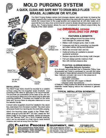
          Manual Vent
          (10-32 F thread)                                      Accessories and Parts) is purchased for use with this valve
                                                                when copper or brass piping is present in the water circulating
                                                                lines. Galvanic corrosion can occur in the presence of:
                                                                       • more noble metals
                                                    Optional           • electrolytic connection
               3/8” NPT(F)                          Locking Pin
               Air Inlet                 Mounting                      • water treatment with copper or bleach
                                         Bracket                       • elevated water temperatures.
                                                                A Dielectric Fitting breaks the electrical connection between
        INSTALLATION:                                           dissimilar metals helping reduce the incidence of galvanic
        The Mold Purge Valve should be mounted to a suitable    corrosion.
        surface using the two supplied angle brackets. Line        TYPICAL INSTALLATION SCHEMATIC
        mounting of the valve to rigid pipe is not recommended.
        The brackets are preinstalled at the base of the unit, but
        may be moved to either end of the valve body for alternate
        mounting positions. If brackets are located at the valve
        body end, be sure there is adequate clearance to move
        the selector handle.
        A check valve (supplied) should be installed in the return
        line, downstream from the return manifold. The check valve
        will prevent fluids from backing into the mold after purging.
        Attach the incoming water supply to the “Water Inlet”.
        Attach shop air to the 3/8” NPT “Air Inlet”, attach the “Air/
        Water Outlet” to the supply manifold. Vented air escapes
        from the “Manual Vent” via a 10-32 threaded opening,
        which can be connected to a drain tube to route residual
        moisture and vent air away from the floor.

                  PLASTIC PROCESS EQUIPMENT, INC.                                            www.ppe.com
                                                                                            e-mail: sales@ppe.com
                   E 8303 CORPORATE PARK DRIVE         W  6385 MONTESSOURI STREET
                  A MACEDONIA, OHIO 44056-2300         E  LAS VEGAS, NEVADA 89113-1186  Toll Free: USA, Canada & Mexico
                   S 216-367-7000 • FAX: 216-367-7022  S  702-433-6385 • FAX: 702-433-6388  800-362-0706
                   T TOLL FREE: 800-321-0562            T  TOLL FREE: 800-258-8877         Order Fax: 800-223-8305
        636

